Pune
+918087586263

'lvdt type inductive measuring probe'

Items tagged with 'lvdt type inductive measuring probe'

product image
DRO UNIT

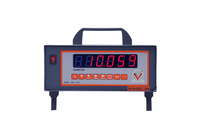
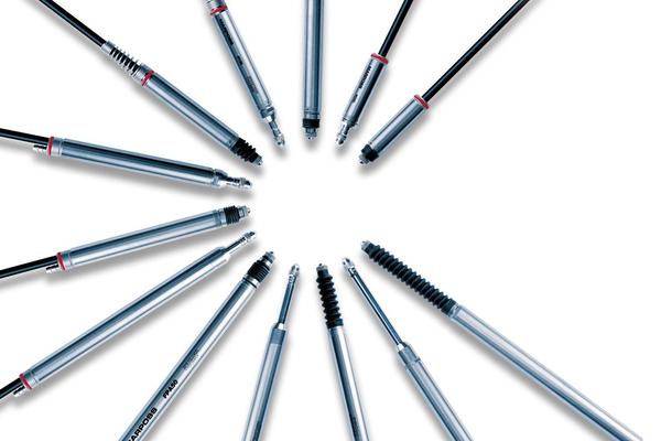
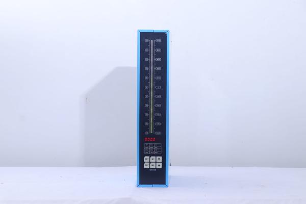
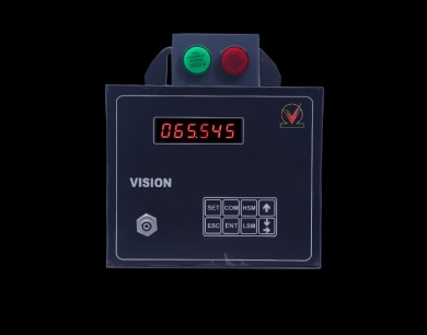
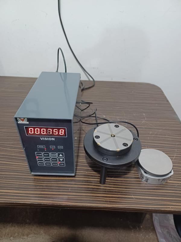
A DRO (Digital Readout) gauge unit! A DRO gauge unit is a digital measuring device used to display the position or dimension of a workpiece on a machine tool, such as a lathe, milling machine, or grinder. It provides precise measurements, improving accuracy and efficiency in various manufacturing and engineering applications. Key Components: 1. Display Unit: Shows measurements in numeric format. 2. Scales or Encoders: Measure linear or rotary motion. 3. Probes or Sensors: Detect position or dimensions. Types of DRO Gauge Units: 1. Linear DRO: Measures linear movement (e.g., X, Y, Z axes). 2. Rotary DRO: Measures angular movement (e.g., rotational position). 3. Combination DRO: Offers both linear and rotary measurements. Features and Benefits: 1. High accuracy (typically ±0.001-0.01mm). 2. Easy readability with large LCD displays. 3. Fast measurement updates. 4. Multiple units (e.g., inches, mm). 5. Data output options (e.g., USB, RS232). 6. Tolerance alarms for precision control. Applications: 1. Machining and manufacturing. 2. Quality control and inspection. 3. Aerospace and automotive industries. 4. CNC machine tools. 5. Precision engineering. Single channel gauge units with selectable probe Inch and Metric measuring ranges RED, GREEN and YELLOW tolerance lamps for REJECT, ACCEPT and REWORK indications RS232 data output Comprehensive outputs for further processing Compatible with Half-bridge and LVDT type inductive measuring probes Sturdy, Ergonomic design, suitable for shop floor environment Splash proof and sealed against dust Add-on Modules available for various applications e.g. Light Grading Module, Relay Module, etc. Mains supply 230 volts AC

Send Message
product image
DRO UNIT

State-of-the-art technology with host of features, a must for today’s shop process quality engineering Two level password, prevents unauthorized alteration Multiple-level display intensity for operators comfort Inch & metric measuring ranges Static & dynamic measurement Permits incorporation of complex formulae for probe combination Display of tolerance and control limit status – supports process control Classifies tolerance band into uniform or non-uniform tailor made grades Permits menu entries up to 16 different settings for quick application changeover Wide range of process control based electrical outputs facilitates automation Auto calibration Compatible with half bridge and LVDT type inductive measuring probe RS232 based interface with real time tagged measurements Aesthetically appealing, sturdy and ergonomic design, suitable for shop-floor applications USB interface to PC and flash drive

Send Message
product image
PIN GAUGE

A pin gauge, also known as a pin gage, is a precision measuring tool used to measure the diameter or width of holes, slots, or other features on a workpiece. It typically consists of a set of cylindrical pins of varying diameters that are used to determine the size of a hole or opening. Here are some key facts about pin gauges: Types of Pin Gauges: 1. Standard Pin Gauge: Measures hole diameters in increments (e.g., 0.001 inches). 2. Tapered Pin Gauge: Measures tapered holes or slots. 3. Ball-Pin Gauge: Uses a ball-shaped tip to measure curved or irregular surfaces. How to Use a Pin Gauge: 1. Select the appropriate pin gauge size. 2. Insert the pin into the hole or slot until it stops. 3. Check the size marked on the pin to determine the measurement. Advantages: 1. High accuracy and precision. 2. Easy to use. 3. Inexpensive compared to other measuring tools. Common Applications: 1. Machining and manufacturing. 2. Quality control and inspection. 3. Aerospace and automotive industries.

Send Message
product image
Electronic Air gauge Unit

1.1 AIR and LVDT PROBE ELECTRONICS COLUMN GAUGE (AIR TRANDUCERS ) / ( AIR PIEZO ) — Single Channel tri color bar graph and Six Digit Display — Inch and metric Ranges — Compatible with Half bridge and full bridge LVDT probe — Absolute / Comparative measurement — Static / Dynamic measurement — Pneumatic converter with 1 input when supplied with this module — Pneumatic converter without flow control valves — RS-232 serial port for PC connectivity — External relay output data saved — Optional — 5000 readings storage facility Range ±0.005 ±0.025 ±0.050 ±0.100 Bar graph L.C. 0.0002 0.0005 0.001 0.002 Six Digit L.C. 0.0002 0.0005 0.001 0.002

Send Message
product image
Electronic Air gauge Unit

Seven segment, 6 character, 3 colour LED display, ½ inch tall Air-Electronic input from All Air Plug and Ring Gauges (APG & ARG) universal type Two metric measuring ranges: (resolution 0.5µm), (resolution 1µm) Measurement display in absolute or comparative form Auto calibration with two setting masters Keyboard entered upper & lower tolerance limits (UTL & LTL), applicable to the values displayed Static or dynamic (max, min, average & TIR) measurements Non-volatile storage of all menu entered values Available in 1 / 2 / 3 or 4 independent channels Combined advantages of non-contact air sensing and high precision electronics RS232 data output available for further processing like machine control through relay output or for SPC AIR SAVING TIMER AND PROXY SENSOR BASE USB DATA SAVE

Send Message
product image
Thread Gauges

In the case of (screw/bolt) threaded parts, thread plug gauges are used in production shops where the “screws” (externally threaded parts) or the “nuts” (internally threaded parts) are to be quickly checked for inspection and approval. When you consider the metrology (the science of measurement) of threaded parts as a whole, more than a couple of thread gage types are involved; a novice in metrology can become somewhat confused with the terminology of the threaded gages in addition to how they are used. In a threaded part, several features are involved – the thread’s major diameter, minor diameter, pitch diameter, pitch (in case of metric threads) or threads per Inch (TPI in case of Standard American Equivalent (SAE) threads), flank angle, etc. Normally, a GO / NO-GO type of threaded gage will inspect a threaded part based mainly on the pitch diameter. As long as a GO gage is answered (threads properly without being forced) and a NO-GO gauge is not answered, the threaded part is deemed to be accepted and pass inspection. In some specific cases where the thread major diameter (for screws) or minor diameter (for nuts) is critical, separate, plain GO/ NOGO gages (like those used for measuring cylindrical parts) are also used in addition to a threaded gages to determine the acceptance of a threaded part. A thread plug gage is used to check acceptance of a “nut” , (an internally threaded part). For small threaded parts, the gage will be double ended, with one end carrying the GO gage and the other end, the NOGO. For larger parts, the two may be separate pieces. A thread plug gage is designed to check the pitch diameter (to the given pitch / Threads per inch). In order for the part to pass inspection and be accepted, the GO gage should pass through the entire length of the nut, without requiring the use of too much rotational force. The NOGO gage can at the best enter into the nut, checked at both ends, over not more than 2 turns. It should not go beyond this.

Send Message

Still searching for
lvdt type inductive measuring probe?