Pune
+918087586263

Gauges

product image
DRO UNIT

State-of-the-art technology with host of features, a must for today’s shop process quality engineering Two level password, prevents unauthorized alteration Multiple-level display intensity for operators comfort Inch & metric measuring ranges Static & dynamic measurement Permits incorporation of complex formulae for probe combination Display of tolerance and control limit status – supports process control Classifies tolerance band into uniform or non-uniform tailor made grades Permits menu entries up to 16 different settings for quick application changeover Wide range of process control based electrical outputs facilitates automation Auto calibration Compatible with half bridge and LVDT type inductive measuring probe RS232 based interface with real time tagged measurements Aesthetically appealing, sturdy and ergonomic design, suitable for shop-floor applications USB interface to PC and flash drive

Send Message
product image
Electronic Air gauge Unit

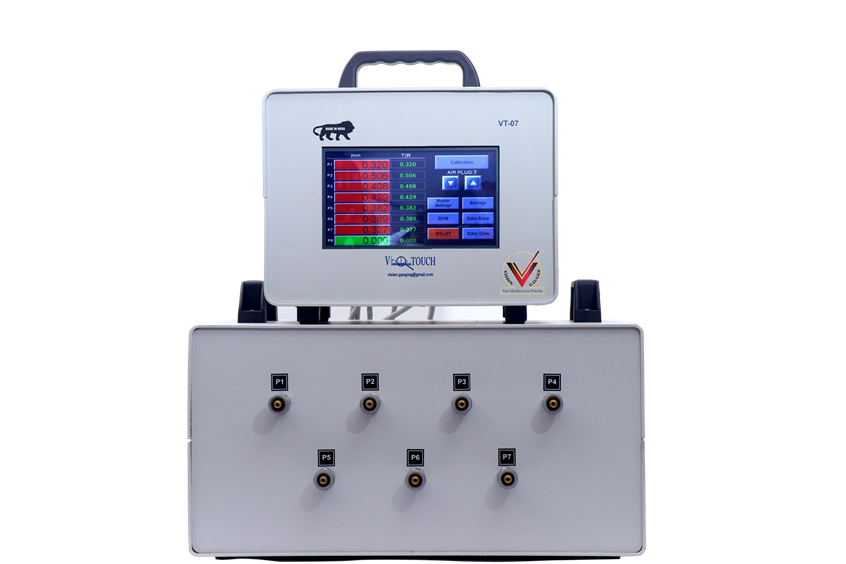
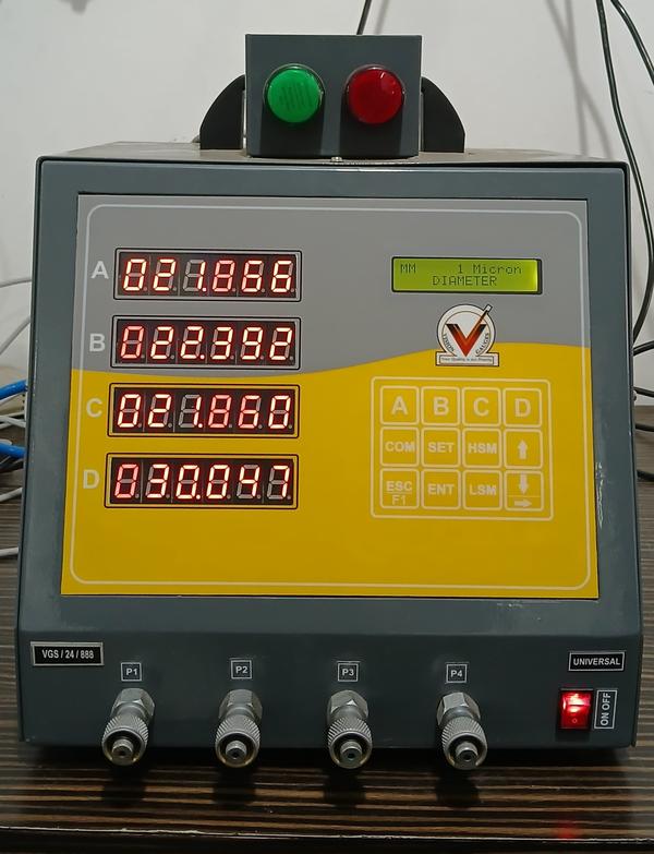
Applications Standard/Honing Dimension Type Linear Resolution 0.1μm/ 1μm Units mm Measurement Modes Current, Min, Max, TIR, AVG Additional results Max, Min, Ovality, and Taper for respective result can be display in run mode as additional results. Result Formula Editor Result formula can be edited for combinations of Piezo channels and / or other results. Indications Pass, Fail, Warning with facility to select require display reading in require colour according to the tolerance band Grade Max 25 Grades available Other Features Machine Stop Massage and Machine stop signal available for reject job condition Calibration Single/Double Master configurable / Force Mastering after N number of measured jobs / Group Calibration for selected result in one group / Auto Mastering is available. Accept Higher and Lower master on inserting into fixture/plug automatically in calibration process Auto Air Cut-Off Yes (Air will become ON after inserting job in Fixture/Plug) Air Saving facility / When nothing is inserted in Fixture/Plug Air will be OFF Measurement process Auto Cycle (After inserting job in Fixture/Plug it will show related Fixture/Plug result) / Measurement Cycle (Sequential measurement) Online SPC Cp, Cpk,

Send Message
product image
ANOLOG AIR GAUGE UNIT

Every gauge carries a calibration certificate giving actual values Module 1A, Module 2A giving the most economical solution to your inspection needs on shop floor High pressure system: high speed of response and self cleaning of gauging area ensures accurate reading of size, taper and ovality at a time Non-contact gauging: long life due to minimal frictional wear Two setting Masters: ensures correct magnification of reading at all times System pressure check gauge: provides a constant check on the system pressure i.e. 3 bars (45 psi) regulated by a high precision regulator built into the unit Minimum line pressure required 4.5 bars (67 psi) Air consumption 46 LPM For diameter 6 mm and above Module-1A air gauge unit is to be used For diameter below 6 mm Module-2A air gauge unit is to be used

Send Message
product image
PLAIN GAUGES

Used for setting of measuring instruments like horizontal comparators, length measuring machines for ID checking, dial bore gauges etc. Made from oil hardening non shrinking gauge steel, hardened and tempered to 60-62 HRC Sub-zero treated at -80 °C for long term dimensional stability Actual dimensions duly etched Calibrated at 20 °C under Standards room condition against national/international traceable standards Certificate of calibration is provided along with each master traceable to national/international standards, certificate under NABL (as per ISO 17025) as per request Master Setting Rings also supplied in standard set consisting of sizes: Set 1: Ø4.0, Ø5.0, Ø6.0 & Ø8.0 mm Set 2: Ø10.0, Ø12.0, Ø16.0 , Ø20.0 & Ø25.0 mm Set also supplied as per customer’s requirement

Send Message
product image
Electronic Air gauge Unit

Features 7 segment tri colour LED display Air Gauge Can directly connected RS-232 serial port for PC connectivity Accuracy ±1% FSD 0.1μm, 0.5μm, 1μm, Least Count Absolute or comparative measurement Tolerance limit setting 2 LED’s showing status Accept-Reject-Rework Built in air regulator for precise pressure Auto ID – OD recognition Compatible with wide range of Air gauges from leading manufacturers Air saving facility as a standard feature for saving costly air Optional — 50000 readings storage facility LOW MAINTANACE

Send Message
product image
Thread Gauges

In the case of (screw/bolt) threaded parts, thread plug gauges are used in production shops where the “screws” (externally threaded parts) or the “nuts” (internally threaded parts) are to be quickly checked for inspection and approval. When you consider the metrology (the science of measurement) of threaded parts as a whole, more than a couple of thread gage types are involved; a novice in metrology can become somewhat confused with the terminology of the threaded gages in addition to how they are used. In a threaded part, several features are involved – the thread’s major diameter, minor diameter, pitch diameter, pitch (in case of metric threads) or threads per Inch (TPI in case of Standard American Equivalent (SAE) threads), flank angle, etc. Normally, a GO / NO-GO type of threaded gage will inspect a threaded part based mainly on the pitch diameter. As long as a GO gage is answered (threads properly without being forced) and a NO-GO gauge is not answered, the threaded part is deemed to be accepted and pass inspection. In some specific cases where the thread major diameter (for screws) or minor diameter (for nuts) is critical, separate, plain GO/ NOGO gages (like those used for measuring cylindrical parts) are also used in addition to a threaded gages to determine the acceptance of a threaded part. A thread plug gage is used to check acceptance of a “nut” , (an internally threaded part). For small threaded parts, the gage will be double ended, with one end carrying the GO gage and the other end, the NOGO. For larger parts, the two may be separate pieces. A thread plug gage is designed to check the pitch diameter (to the given pitch / Threads per inch). In order for the part to pass inspection and be accepted, the GO gage should pass through the entire length of the nut, without requiring the use of too much rotational force. The NOGO gage can at the best enter into the nut, checked at both ends, over not more than 2 turns. It should not go beyond this.

Send Message

Subcategory Tags

Phone Number

Email Address visiongauges@gmail.com

Mon-Thu: 10 AM - 2 PM • Fri: 3 PM - 7AM

Other Website Visit our other website